Insulation and earthing tests
Check the plant is safe, and leaking no energy to ground. Insulation resistance tests show whether cables and modules are leaking current to ground. Earth resistance and continuity tests show whether the earthing system will protect people and equipment during a fault.
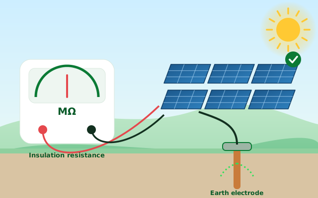
- Inverters report insulation or earth faults
- After monsoon, flooding or rodent damage
- As part of commissioning or yearly safety checks
- Before a lender or insurer review
- Lowers fire and shock risk
- Finds hidden leakage that can trip inverters
- Gives a documented safety record
How we do it, step by step.
Follow lock-out and isolation procedure so the work is safe.
Measure insulation resistance on strings, and continuity of bonding and earthing.
Measure earth resistance at pits and compare with the design requirement.
List failures, likely causes and the order in which to fix them.
- Pass or fail result for every tested circuit and earth pit
- A list of weak cables, connectors and earth pits
- Clear actions for repair and retest
Outcomes depend on what the inspection finds. Possibilities are labelled as such in every report.
- Readings table with locations
- Photos of tested points
- Retest checklist
Instruments: Insulation tester, earth resistance tester, continuity meter
A mobile lab tests modules across 280 MWp of Indian plants
The lab was meant to support warranty and insurance claims on delivery, claims against installers during construction, and replacement of weak modules during operation.
Read the case →Other services
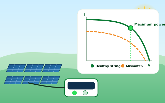
IV curve tracing
Measure what each string and module can really deliver.
See the process and outcomes →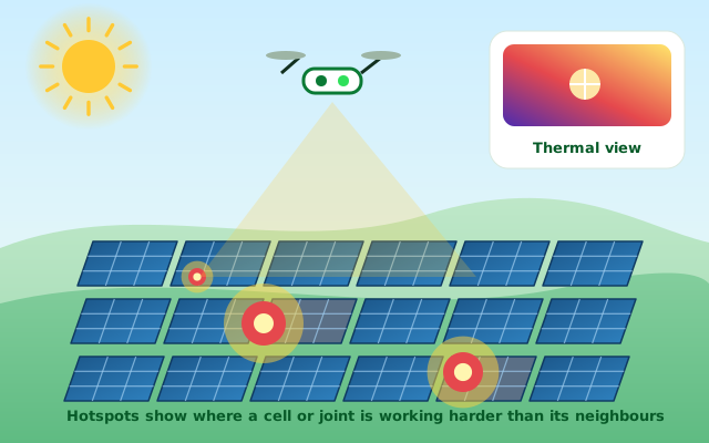
Thermography
See heat problems from the ground or from the air.
See the process and outcomes →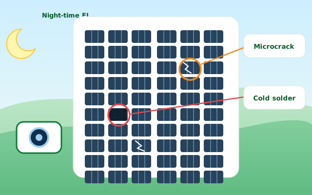
Electroluminescence (EL) imaging
Look inside cells for cracks and bad solder joints.
See the process and outcomes →Want this test on your plant?
Send an enquiry and we will prepare a checklist for your site.